
Introduction to robotics: types of motors
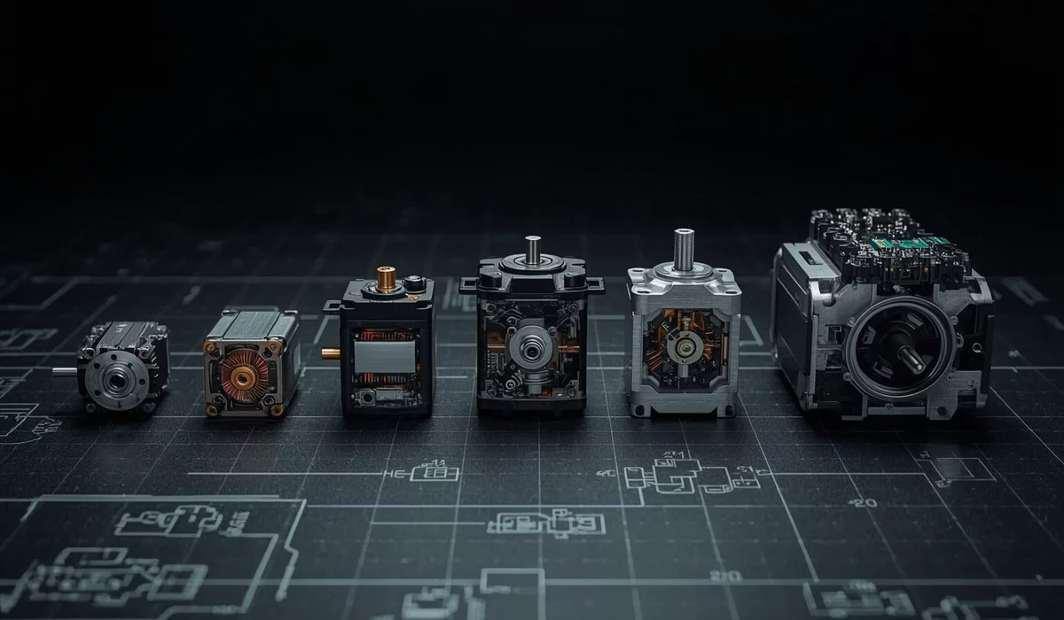
A motor is what turns code into motion. Everything else depends on the choice of motor: what power supply is needed, which controller, which bus to communicate with it, how much a joint will cost, and whether the robot can even stand up. This article is an overview map: how the main types of motors are built, how to power and control them, where to buy them, and what to choose for three typical tasks—a power platform from 100 kg, a walking robot up to 100 kg, and a wheeled robot up to 30 kg.
Prices are approximate as of September 2026, taken from store websites via the links. In different regions, shipping, VAT, and duties are added.
- Basic concepts: torque, KV, gearbox, FOC
- Map of motor types
- Brushed DC motors
- Hobby servos and smart servos
- Brushless (BLDC) for drones
- Gimbal motors (direct drive)
- BLDC + encoder + planetary gearbox + ODrive
- QDD and integrated actuators
- Stepper motors
- Hub motors
- Power: AC servos, worm, linear
- Summary table
- Software control
- Many motors: buses and wiring
- Power supply
- Scenarios: 100+ kg, walking, wheeled
Basic concepts
To read datasheets, a dozen terms are enough.
Torque (N·m)
Rotational force. 1 N·m is 1 newton at a 1 meter lever arm, that is, about 100 g suspended at the end of a one-meter lever, or 10 kg at a 1 cm arm. Servos are often rated in "kg·cm": 30 kg·cm ≈ 2.9 N·m.Peak and continuous
The continuous (nominal) torque can be held for a long time without overheating. Peak torque is for seconds. For jumping, peak is important; for standing and lifting loads, continuous matters.KV (rpm per volt)
No-load speed per volt. Low KV means slower, but more torque per amp. Kt (N·m/A) ≈ 8.27 / KV.Gear ratio
A 10:1 gearbox multiplies torque by about 10 times (minus losses) and divides speed by 10. But friction, backlash, and motor inertia are also multiplied.Backdrivability
Whether you can turn the output by hand. With a 1:300 gearbox—you can't; with 1:6—easily. This is important for walking robots: the joint should "spring" when hitting the ground.Encoder
Angle sensor. Incremental counts steps from start, absolute knows the angle right after power-on. Magnetic absolute (AS5047, MA702) cost 10–20 €.FOC
Field Oriented Control is an algorithm that precisely doses current in the three phases of a BLDC based on rotor angle. It provides quiet operation, smooth torque at zero speed, and current (i.e., torque) control.Control loops
Position → speed → current. Good drivers have all three, and you can set any target: angle, speed, or torque.Motor type map
Roughly all motors for robots are divided along two axes: whether there are brushes (brushed or brushless), and how much integration is in the housing (bare motor → motor with gearbox → motor with gearbox, encoder, and driver, communicating over a bus). The more integration, the more expensive the unit, but the fewer wires and less debugging.
| Type | Price per joint | Main advantage | Main disadvantage | Where to get |
|---|---|---|---|---|
| Brushed + gearbox | 5-60 € | Simple: two wires and an H-bridge | Brushes wear out, no feedback without encoder | Wheeled robots up to 30 kg |
| Hobby servo (PWM) | 3-60 € | Ready-to-use positioning out of the box | Noisy, backlash, no feedback to software | Toys, grippers, small manipulators |
| Smart servo over bus | 15-500 € | Bus, feedback on angle/current/temperature | Large gearbox - not backdrivable | Desktop arms (SO-ARM101, LeRobot), small humanoids |
| BLDC (drones) | 15-100 € | Huge power-to-weight ratio | High RPM, requires ESC or FOC driver | Propellers, base for DIY actuators |
| Gimbal | 20-60 € + driver | Direct drive, smooth, quiet | Low torque | Cameras, lightweight joints, demos |
| BLDC + encoder + planetary gearbox | ~150-250 € assembled | Cheap, flexible, open source | A lot of assembly and tuning | DIY walking robots, research |
| Integrated QDD actuator | 120-600 € | Single cable: power + CAN; transparent joint | Expensive per unit, closed firmware | Walking robots, humanoids, exoskeletons |
| Stepper | 10-50 € + driver 5-40 € | Precise positioning without encoder | Loses steps, heats up when holding, weakens at speed | 3D printers, CNC, linear axes |
| Hub motor (wheel hub) | 30-150 € | Wheel, motor, and bearing in one | Requires FOC driver, heavy | Wheeled platforms 20-300 kg |
| AC servo / worm / linear | 100-1000+ € | Industrial reliability and power | Heavy, often 220 V, slow (worm) | Lifts, power platforms from 100 kg |
Brushed DC motors
Brushes switch the current, not the field rotation with the shaft
The stator magnets are stationary: the field in the gap is directed from N to S. The windings and copper commutator plates rotate with the shaft, but the brushes remain on the housing. When another plate comes under the brush, the current path changes. Therefore the total field of the windings remains roughly perpendicular to the stator field, even though the coils themselves have already turned. The torque continues to pull the shaft in one direction.
The commutator switches the current when the brush moves to the next segment.
Model: three identical windings are connected in a triangle between plates 1-2, 2-3, and 3-1. The A/B/C colors link the coils and currents; a red/blue end means N/S. Inductance, brush width, and sparking are not modeled. In this rough scheme, the angle changes from 60° to 120°, torque ∝ sin(angle). More windings and segments mean less ripple around 90°. The speed here is set for clarity, not calculated from torque.
The oldest and simplest type. Connect it to a battery—it spins, reverse the polarity—it spins the other way. A bare brushed motor is too fast (5–15 thousand rpm) and weak, so for robots you almost always buy a gear motor: motor + metal gearbox + optionally a Hall encoder on the shaft.
- Voltage 6–24 V
- Current 0.1–10 A (stall current up to 20+ A)
- Gear ratio 10:1 – 300:1
- Torque 0.1–10 N·m at output
- Efficiency 40–70% with gearbox
- Brush lifespan ~1000–3000 h
Pros
- Cheap and available everywhere
- Control—two wires and an H-bridge with PWM
- High torque at low speed thanks to the gearbox
- Often available in versions with encoder
Cons
- Brushes wear out, spark, and create electromagnetic interference
- Not backdrivable with a large gearbox
- No precise torque control
- Lower efficiency than BLDC
Best suited for
Wheeled robots up to 20–30 kg, tracked platforms, conveyors, grippers, rotary mechanisms. An excellent first motor for learning.Controllers and libraries
- H-bridge drivers: DRV8871 / TB6612FNG (up to ~1-3 A), Cytron MDD10A / MDD20A (10 / 20 A per channel), RoboClaw (2x15 - 2x160 A, counts encoders and handles PID itself, has Python and ROS drivers), Sabertooth. It's better not to use the old L298N: it loses 2-4 V across itself and gets hot.
- Software: on Arduino/ESP32 it's just
analogWrite()+ two direction pins; encoders - theEncoderlibrary or ESP32 hardware counter (PCNT). For ROS 2 -ros2_controlwithdiff_drive_controller.
Where to buy
- Pololu 37D - classic: 12 or 24 V, from 6.3:1 to 150:1, with encoder; 30:1 gives 330 rpm and ~14 kg·cm at 12 V. About $40-60.
- goBILDA Yellow Jacket - planetary gearmotors with built-in encoder, $54.99; convenient mounting ecosystem.
- AliExpress: JGB37-520, JGA25-370 series with encoder - 8-15 €, but quality varies greatly.
Hobby servos and smart servos
Signal period 20 ms (50 Hz): pulse 1.0 ms - 0°, 1.5 ms - 90°, 2.0 ms - 180°. Dashed horn - target, white - actual shaft. Load pulls the horn toward 0°. The model is simplified: gearbox is drawn as 43:1 (real servos are 100-300:1, so in the picture the motor spins slower than in reality), time is slowed down 5x, motor is a first-order model with friction. Dead zone and frequencies are typical values; actual servos may differ.
A servo is a brushed (less often brushless) motor with a gearbox and an angle sensor in a single housing. You say “move to 90°” — it moves and holds. The gearbox is usually very large, from 30:1 in fast servos to 300:1 in high-torque ones, so the torque is decent, but you can't turn the output by hand, and the gears are noisy.
Analog and digital
Analog servos control the motor at the input signal frequency (50 Hz): softer, quieter, but with a “dead zone” and worse holding.Digital process the same PWM signal with a microcontroller and send pulses to the motor hundreds of times per second: more precise, hold position better, but consume more power and have a characteristic whine. From a software perspective, there is no difference — both are controlled the same way.
Smart servos via bus (serial bus servo)
The next level: instead of PWM — half-duplex UART or RS-485, each servo has its own ID, all are connected in a daisy chain on a single cable. You can not only set the angle, but also read the current angle, current, temperature, voltage; there is a wheel mode and a torque limit mode. Popular open-source robotic arms are built on such servos LeRobot SO-ARM100/101.
- Hobby: 4.8-8.4 V
- Bus: 7.4-14.8 V
- Torque 0.2-6 N·m (2-60 kg·cm), brushless up to 50+ N·m
- Angle 180°, 270° or 360° + wheel mode
- Current up to 2-3 A per servo at stall
Pros
- Out-of-the-box positioning
- No drivers needed (hobby) or a single USB-UART adapter (bus)
- Bus servos are easy to connect by the dozen
- Very cheap: STS3215 for $16
Cons
- Noisy, with backlash
- Large gearbox — no compliance, impacts break gears
- A hobby servo provides no feedback about itself
- Weak torque control
Best suited for
Grippers, desktop manipulators, heads and arms of small humanoids, robot dogs up to 2-3 kg, animatronics. For legs heavier than ~5 kg, it's already problematic: the gearbox can't withstand impacts.Where to buy
- Feetech STS3215 (12 V, 30 kg·cm, magnetic encoder) - about $16; the same one from Waveshare as ST3215 - $21.90. There are also brushless versions there with 450-1000 kg·cm for $399-650.
- ROBOTIS Dynamixel - the benchmark for smart servos with excellent documentation: XL430 from ~€50-60, X/XM series hundreds of dollars, Pro - thousands.
- Hobby servos: MG996R (clone, €3-5), Savöx, Hitec, KST - from €20 to €100+.
Controllers and libraries
- Hobby servos directly: Arduino
Servo, ESP32ESP32Servo. More than 4-6 servos - PCA9685 board (16 channels via I²C, ~€5) + Adafruit PWM Servo Driver oradafruit-circuitpython-servokiton Raspberry Pi. - Dynamixel: Dynamixel SDK (C++, Python, ROS 2), U2D2 adapter.
- Feetech: SCServo SDK from the manufacturer, driver in LeRobot; adapter - Waveshare Bus Servo Driver Board or any USB-UART with half-duplex circuit.
Brushless (BLDC) motors for drones
A brushless motor is an 'inside-out' brushed motor: the windings are stationary, the magnets rotate, and the controller switches the current. This results in high efficiency (80-90%), no brush wear, and huge specific power. Drone motors are optimized for high RPM with a propeller, so they have a high KV (900-2500), and for robots they are used either with a gearbox or low-KV 'fat' models are chosen (5010, 6374, 8308, 8318).
- Designation 2207, 5010, 8308 = stator diameter × height in mm
- KV 50-2500
- Voltage 2S-12S LiPo (7.4-44 V)
- Current 10-80 A
- Power 100 W - 3+ kW
How three sine waves rotate the magnetic field
A coil on a stator tooth is an electromagnet. The controller applies voltage to it (actually a fast PWM, whose average is a sine), and due to inductance, the current in the coil rises smoothly and follows this sine wave. Current in one direction makes the tooth tip an S pole, in the other direction an N pole, and the pole strength is proportional to the current. Three coils are placed 120° apart, their fields add up as vectors—and if the currents are also phase-shifted by 120°, the sum is a single field of constant strength, which rotates smoothly. The rotor magnet follows it.
Press 'Pause' and move the angle slider to examine individual moments. Switch the mode to compare FOC with a simple ESC.
Pros
- Best power and torque per gram
- No brushes – long lifespan, silent
- Cheap: 15-60 € per motor
- Huge selection
Cons
- Controller required (ESC or FOC)
- By itself, fast and weak at low RPM
- A cheap ESC can't hold position and starts poorly under load
Best suited for
Drones and propellers. In robotics – as the “heart” of DIY actuators (see below), for wheels via gearbox, for throwing and jumping mechanisms.Controllers
- ESC for drones(firmwares BLHeli_32, Bluejay, AM32) – controlled by PWM, DShot, PWM. Speed only, no position. 10-40 €.
- VESC- open-source controller for electric skateboards and robotics: FOC, Hall sensors or encoder, CAN, UART; 50-200 € at Flipsky, Trampa, MakerX. Excellent for wheels.
- FOC drivers for joints- ODrive, moteus, Tinymovr, SimpleFOC: see the following sections.
Where to buy: T-Motor(including the series for robots), iFlight, BrotherHobby, Flipsky (63xx motors for skateboards), AliExpress (Eaglepower 8308/8318, Maytech).
Gimbal motors: direct drive without gearbox
These are BLDCs wound with thin wire and a high number of turns: phase resistance 5-15 Ohm instead of 0.05-0.2 Ohm for drone motors. They are slow and weak (usually 0.05-0.3 N·m), but can be powered with low current, smoothly hold any angle, and rotate without a single gear. The combination of “motor directly on the joint” is called direct drive.
- Typical: GM2804, GM3506, GM4108, GM5208
- Phase resistance 5-15 Ohm
- Current 0.3-2 A
- Torque 0.05-0.5 N·m
- 12-24 V
Pros
- Zero backlash and gear noise
- Perfect transparency – the joint senses external force through current
- Fast response
- Can be powered by cheap low-current drivers
Cons
- Weak: can't hold an arm heavier than a few hundred grams
- Requires FOC controller and encoder
- Holding weight = constant current = heating
Where it's best
Camera stabilizers, haptic knobs with force feedback, lightweight demo manipulators, balancing cube robots (reaction wheel), educational FOC projects.Controllers and prices
- Tinymovr R5.4(now the Motionlayer brand) - FOC controller the size of a motor, mounts directly on the rear cover, built-in encoder, CAN; €88, starter kit - €124. Python library
tinymovrand GUI Studio. - SimpleFOC - open-source FOC library for Arduino/STM32/ESP32 and cheap SimpleFOC Shield / Mini boards (10-30 €). The best way to get hands-on experience with FOC.
- Motors themselves: iFlight iPower GM series, T-Motor GB series, AliExpress - 20-60 €.
BLDC + magnetic encoder + planetary gearbox + ODrive
The classic approach for DIY walking robots since the MIT Mini Cheetah: take a thick low-KV BLDC, glue a diametrically magnetized magnet to the shaft, place a magnetic encoder board opposite, add a 3D-printed or purchased planetary gearbox 6:1 - 10:1, and control everything via an FOC driver. You get a joint similar to a commercial QDD, but 1.5-3 times cheaper and fully under your control. A classic breakdown of such a design is Ben Katz's master's thesis «A low cost modular actuator for dynamic robots» (MIT, 2018).
What makes up the price
| Component | Example | Price |
|---|---|---|
| Motor | Eaglepower 8308 / Flipsky 6374 / ODrive M8325s | ~30-90 € |
| Magnetic encoder | AS5047P, MA702 breakout, CUI AMT102 (incremental) | +15-25 € |
| Controller | ODrive S1 $149, ODrive Micro $89, moteus r4.11 ~$86-99, Tinymovr €88 | ~80-150 € |
| Gearbox | 3D-printed planetary/cycloidal, or ready-made 1:6-1:10 | 5-80 € |
| Bearings, fasteners | thin-walled bearings 6808/61808 etc. | 10-20 € |
| Total per joint | ~150-300 € |
ODrive S1 / Pro / Micro
The most popular ecosystem. S1: 12-48 V, up to 1.6-2 kW, built-in encoder on the board, CAN, USB, UART, STEP/DIR. Python packageodrive and web GUI. There are ready-made 'S1 + M8325s motor' kits from $279. Supports hoverboard hub motors.mjbots moteus
A tiny board with a built-in absolute encoder, power and CAN-FD are daisy-chained. Very good documentation and Python/C++ libraries, used in the quadruped Quad A1 and many humanoids. Note: requires CAN-FD (fdcanusb or pi3hat), a regular CAN adapter will not work.Tinymovr / SimpleFOC
Tinymovr is a compact controller mounted on the back of the motor, CAN 1 Mbit/s. SimpleFOC is a library for custom boards on STM32/ESP32. Good for learning and lightweight joints.QDD and fully integrated actuators
Quasi-direct drive (quasi-direct drive) is a compromise between direct drive and servo: a powerful flat BLDC with a small gearbox 6:1 - 10:1. This is enough to multiply the torque to the required values, but the gear ratio is still low enough that the joint remains backdrivable: you can turn it by hand, and the driver "feels" the external force through the current—without a separate torque sensor. For walking robots, this is critical: the leg softly absorbs the impact with the ground, instead of breaking gears like a servo.
A fully integrated actuator is a QDD (or planetary with a higher gear ratio), in which the motor, gearbox, encoder, sometimes a second output encoder, driver, and temperature sensor are all assembled into one "thick cylinder." Only two power wires and a pair of CAN wires come out. All motors on the leg are daisy-chained to a single bus.
Planetary gearbox, gear ratio, and joint transparency
The sun gear is mounted on the motor shaft, the ring is stationary, and the output is taken from the carrier: i = 1 + Zring / Zsun. The load is shared by three planet gears, so one stage is compact and can handle high torque. Change the gear ratio and push the output "by hand": you can see how the force increases and how sensitivity to the outside world disappears.
Educational model, not a calculation for a specific actuator: motor 1 N·m, stage efficiency 97%, motor mass 0.3 kg + 0.08 kg per stage, gearbox friction increases with gear ratio conditionally. During the push, the driver is in zero-torque mode and only measures current. For 36:1 and above, the first stage is shown, and the "output" arrow accounts for all.
- Power supply 24-48 V
- Nominal 3-40 N·m, peak 9-120+ N·m
- Mass 0.3-2.5 kg
- Speed 100-500 rpm at output
- CAN 1 Mbit/s or CAN-FD, sometimes RS-485 / EtherCAT
- Modes: position, speed, torque, 'MIT mode' (impedance)
Pros
- Backdrivable, shock-resistant, fast
- Torque control without a torque sensor
- Minimal wiring: power + CAN in a chain
- Quieter than servos: few gears, and they are large
- Ready to use out of the box
Cons
- Expensive: from ~€120 to €600 per joint
- Closed firmware, different protocols for different brands
- Consumes current and heats up constantly when holding position
- Heavier than servos for the same torque at small sizes
Best suited for
Quadruped and biped robots, humanoids, exoskeletons, collaborative arms, force feedback (teleoperation), any joints that interact with the world.Popular manufacturers and prices
| Model | Peak / nominal | Gearbox | Weight | Bus | Price |
|---|---|---|---|---|---|
| CubeMars AK60-6 | ~9 / 3 N·m | 6:1 | ~380 g | CAN, UART | $298.90 |
| CubeMars AK70-10 | 24.8 / 8.3 N·m | 10:1 | 621 g | CAN | from $398.90 |
| CubeMars AK80-9 | 22 N·m peak | 9:1 | ~500 g | CAN | see store |
| Damiao DM-J4310-2EC | ~7 / 3 N·m | 10:1 | ~300 g | CAN, 2 encoders | ~€120 |
| RobStride RS02 | 17 / 7 N·m | 7.75:1 | 380 g | CAN | ¥699 in China |
| RobStride RS03 | 60 / 21 N·m | 9:1 | 900 g | CAN | ¥999 in China |
| Unitree GO-M8010-6 | 23.7 N·m peak | 6.33:1 | ~530 g | RS-485 | $369 |
RobStride prices in yuan - the official manufacturer price list; European resellers are noticeably more expensive. RobStride also offers the RS04 at 120 N·m for large humanoids. Also worth checking out are MyActuator (RMD-X series, CAN/EtherCAT) and SteadyWin (GIM). CubeMars notes that the AK series (integrated driver) and AKE series (QDD without driver, 'bare' module for your own controller) are different product lines.
CAN: how to communicate with them
Almost all integrated actuators communicate via CAN. This is a differential pair CANH/CANL, up to 1 Mbit/s (CAN-FD - up to 5-8 Mbit/s in the data phase), up to ~110 nodes on the bus, with two 120 Ohm terminators at the ends. Each motor is assigned its own ID, and all are connected to the same cable.
- USB-CAN adapter: CANine from Motionlayer - €34.50, USB-C, CAN 2.0A/B up to 1 Mbit/s, built-in switchable terminator, firmware slcan or candleLight (then in Linux it is a regular
can0via SocketCAN). Compatible with Jetson Orin Nano, Raspberry Pi, laptop. Alternatives: CANable, PEAK PCAN-USB, Waveshare USB-CAN. - Built-in CAN on Jetson Orin: Orin modules have a CAN controller (driver
mttcan), but you need an external transceiver like SN65HVD230 and pinmux configuration. The USB adapter is usually faster to set up. - CAN-FD (for moteus): mjbots fdcanusb or pi3hat for Raspberry Pi with several independent buses - convenient to assign a bus to each leg.
- Unitree uses RS-485 - requires a USB-RS485 adapter and their SDK.
Stepper motors
Full step, half step, microstep, and position loss
Two phases create a field with A and B components. Full step sharply changes its direction, half step adds intermediate positions. In microstepping, the currents IA = cos(θ), IB = sin(θ) break this transition into small increments. The toothed rotor follows the field, but only as long as there is enough torque.
Educational model, not a dynamics calculation: four tooth periods per revolution, so the full step is increased to 22.5° (a typical hybrid motor has 1.8°). Four large teeth emphasize periodicity; phase positions are schematic, this is not a drawing of a real hybrid motor stator. If the load exceeds 100%, the shaft is locked by a brake, but commands continue. After releasing the brake, the rotor is captured by the nearest stable position, but missed rotations of the electric field are not restored. We see the error; the driver without an encoder does not know about it. “Reset position” conditionally performs a zero search, not just resetting the STEP counter.
A stepper motor moves in discrete steps. The driver receives two signals: STEP (one pulse = one step) and DIR (direction). The number of steps is the position, so no encoder is needed. Sizes are standardized: NEMA 17 (42 mm, 3D printers), NEMA 23 (57 mm, CNC), NEMA 34 (86 mm, machines).
- 1.8° (200 steps) or 0.9°
- Microstepping up to 1/256
- NEMA 17: 0.4-0.6 N·m
- NEMA 23: 1-3 N·m
- NEMA 34: 4-12 N·m
- Driver 12-48 V (and higher for NEMA 34)
Pros
- Accurate position without encoder
- High torque at low speeds, holds load in place
- Inexpensive, standard sizes and mounts
- Simple STEP/DIR control
Cons
- Missed steps without feedback
- Current always flows – heats up even when stationary
- Resonance, vibration, noise (solved by TMC drivers)
- Heavy for its torque, weakens at speed
- Not backdrivable, poor for dynamics
Best suited for
Linear axes (belt, screw), 3D printers, CNC, rotary tables, desktop manipulators with slow movements, dispensers, camera focusing. Not for legs.Drivers and libraries
- TMC2209 (BigTreeTech and others, 5-10 €) – up to 2 A RMS, 4.75-28 V, StealthChop (almost silent), StallGuard (stall detection without limit switch), UART configuration. Library TMCStepper.
- For NEMA 23/34 – DM542 / DM556 or closed loop StepperOnline CL57T ($33-51): encoder on the motor, steps are not lost.
- Pulse generation: AccelStepper (acceleration and deceleration), FastAccelStepper (hardware timers ESP32/AVR, up to tens of kHz), Klipper / grblHAL / FluidNC firmware for multi-axis systems.
Where to buy: StepperOnline - everything from NEMA 8 to 34, NEMA 17 closed loop kit + driver $46.64; LDO Motors, Moons', Trinamic/ADI.
Hub motors
BLDC outrunner, where the bell is actually the wheel rim with the tire. The most affordable source is hoverboards: 6.5" wheel, 36 V, ~250-350 W, Hall sensors, a pair of used wheels from the market costs next to nothing. New 6.5-10" hub motors with encoder for AGV are sold on AliExpress for about $120-130 per unit with a claimed load capacity of up to 200 kg per wheel.
Pros
- No gearbox, chains, or belts—nothing to break
- High torque at low speed (10-20+ N·m)
- Bearings are rated for human weight
- Quiet, with regenerative braking
Cons
- Heavy (2.5-4 kg each)
- Hall sensors are coarse—for precise positioning at standstill, an encoder is needed
- Requires FOC driver at 36-48 V
Best suited for
Wheeled platforms 20-300 kg: garden robots, delivery carts, “follow-me” platforms, AGVs, mobile manipulator bases.- Drivers: ODrive (S1 per wheel, Pro for heavy loads; ODrive has a guide for hoverboard motors), VESC, or the native hoverboard board with hoverboard-firmware-hack-FOC firmware (FOC, UART control)—an almost free driver for two wheels.
Power drives: AC servos, worm gears, linear actuators
When you need to lift or carry hundreds of kilograms, reliability, brakes, and safety take precedence over dynamics and responsiveness.
Industrial AC servos
Synchronous motor with absolute encoder (17-23 bit) and separate servo driver, 220 V AC or 48 V DC, control via STEP/DIR, RS-485 (Modbus), CANopen, or EtherCAT. With a planetary gearbox 10:1 - 50:1, it delivers hundreds of N·m. StepperOnline A6 750 W with driver - from $116, for Delta, Leadshine, Yaskawa - more expensive. Versions with electromagnetic brake are available.Worm gear motors
Brushed or BLDC motor with a worm gear 30:1 - 100:1. The main feature is self-locking: without power, the load does not fall. Drawbacks - efficiency 40-70%, slow, heats up. This also includes wiper motors (12 V, ~10-20 N·m, cheap at junkyards) - a favorite choice for robot battles and DIY lifts.Linear actuators
Motor + screw drive: pushes a rod with a force of 500-10,000 N (50-1000 kg). Built-in limit switches, often a potentiometer or Hall sensor for feedback, self-locking. Controlled like a brushed motor (H-bridge). Progressive Automations, Actuonix (miniature), AliExpress for 30-100 €.BLDC for electric transport
Electric skateboard motors (63xx-80xx), scooter hub motors, e-bike with VESC or ODrive Pro. The best choice for 'a lot of power for reasonable money' for 100-300 kg platforms.Summary table
| Brushed | Servo | BLDC + FOC | Gimbal | QDD | Stepper | Hub | |
|---|---|---|---|---|---|---|---|
| Noise | medium | high | low | very low | low | medium* | low |
| Backdrivable | depends on gearbox | no | yes | yes | yes | no | yes |
| Torque control | coarse | no / coarse | precise | precise | precise | no | precise |
| Feedback | opt. encoder | bus-based - yes | encoder | encoder | built-in | no (or closed loop) | Halls / encoder |
| Interface | PWM + DIR | PWM / UART | CAN / UART / USB | CAN / SPI | CAN / CAN-FD | STEP/DIR, UART | CAN / UART / PWM |
| Power supply | 6-24 V | 5-14 V | 12-56 V | 12-24 V | 24-48 V | 12-48 V | 24-48 V |
| Many units | driver for each | bus - easy | bus | bus | bus - very easy | driver for each | bus |
| Startup complexity | ★☆☆ | ★☆☆ | ★★★ | ★★☆ | ★★☆ | ★☆☆ | ★★☆ |
* With a TMC driver in StealthChop mode, a stepper is almost silent at low speeds.
Software control
From a programmer's perspective, there are five interface levels. The higher the level, the less real-time is needed in your code.
| Interface | Who | What you send | Do you need realtime in your code |
|---|---|---|---|
| PWM + DIR | brushed, ESC, hobby servos | duty cycle or pulse length | yes, if you close the loop by encoder yourself |
| STEP / DIR | stepper, AC servos | pulse stream | yes, pulse generation (MCU timers) |
| UART / RS-485 | bus servos, Unitree, Modbus | commands with ID: angle, speed | no, 100-1000 Hz is enough |
| CAN / CAN-FD | ODrive, moteus, Tinymovr, CubeMars, Damiao, RobStride | position, speed, torque, Kp/Kd | soft: 200-1000 Hz on Linux |
| EtherCAT | industrial servos, expensive actuators | cyclic process data exchange | yes, RT kernel (IgH, SOEM) |
Hobby servo on Arduino
#include
Servo s;
void setup() { s.attach(9); }          // signal wire to pin 9
void loop() {
  s.write(0);   delay(1000);           // 1.0 ms pulse
  s.write(180); delay(1000);           // 2.0 ms pulse
}
Stepper with TMC2209 and AccelStepper
#include
AccelStepper st(AccelStepper::DRIVER, 2, 3);  // STEP=2, DIR=3
void setup() {
  st.setMaxSpeed(4000);       // steps/s (including microstepping)
  st.setAcceleration(8000);
  st.moveTo(3200);            // 1 revolution at 1/16 microstep
}
void loop() { st.run(); }     // call as often as possible
ODrive from Python (firmware 0.6)
import odrive
from odrive.enums import AxisState, ControlMode

odrv = odrive.find_any()                      # USB
ax = odrv.axis0
ax.controller.config.control_mode = ControlMode.POSITION_CONTROL
ax.requested_state = AxisState.CLOSED_LOOP_CONTROL
ax.controller.input_pos = 2.5                 # in motor revolutions
print(ax.pos_vel_mapper.pos_rel, ax.motor.foc.Iq_measured)
On the robot, CAN is used instead of USB (CANSimple protocol, there is a package odrive_can for ROS 2).
moteus via CAN-FD
import asyncio, math, moteus

async def main():
    c = moteus.Controller(id=1)
    await c.set_stop()                        # reset errors
    while True:
        state = await c.set_position(position=math.nan, velocity=0.5,
                                     maximum_torque=2.0, query=True)
        print(state.values[moteus.Register.POSITION])
        await asyncio.sleep(0.01)

asyncio.run(main())
"MIT mode" (CubeMars, Damiao and many clones)
The most common protocol for QDD came from Mini Cheetah. In a single 8-byte CAN frame, you send the desired position, speed, stiffness Kp, damping Kd, and direct torque. The driver itself calculates τ = Kp·(p_des - p) + Kd·(v_des - v) + τ_ff at its own frequency. This is impedance control: small Kp - soft "springy" leg, large - stiff.
import can

def f2u(x, lo, hi, bits):                     # float -> unsigned int
    x = min(max(x, lo), hi)
    return int((x - lo) * ((1 << bits) - 1) / (hi - lo))

# Take ranges from your model's datasheet! Here is an example for AK70-10.
P, V, T, KP, KD = 12.5, 50.0, 25.0, 500.0, 5.0

def mit_frame(p, v, kp, kd, t):
    p_i, v_i = f2u(p, -P, P, 16), f2u(v, -V, V, 12)
    kp_i, kd_i, t_i = f2u(kp, 0, KP, 12), f2u(kd, 0, KD, 12), f2u(t, -T, T, 12)
    return bytes([p_i >> 8, p_i & 0xFF, v_i >> 4,
                  ((v_i & 0xF) << 4) | (kp_i >> 8), kp_i & 0xFF,
                  kd_i >> 4, ((kd_i & 0xF) << 4) | (t_i >> 8), t_i & 0xFF])

bus = can.Bus(interface="socketcan", channel="can0", bitrate=1_000_000)
ENTER = bytes([0xFF] * 7 + [0xFC])            # enter control mode
bus.send(can.Message(arbitration_id=1, data=ENTER, is_extended_id=False))
bus.send(can.Message(arbitration_id=1, data=mit_frame(0.5, 0, 20, 1, 0),
                     is_extended_id=False))
print(bus.recv(0.01))                          # response: position, speed, current
Bring up CANine in candleLight mode on Linux: sudo ip link set can0 up type can bitrate 1000000. For slcan firmware use interface="slcan" in python-can.
Libraries and frameworks
- python-can - universal CAN from Python (SocketCAN, slcan, PCAN, Kvaser).
- ros2_control - standard ROS 2 layer: you write (or use a ready-made) hardware interface for your motors, and get trajectory controllers, diff drive, gravity compensation, etc. Ready-made interfaces exist for Dynamixel, ODrive, moteus, CubeMars, Feetech.
- LeRobot - policy learning on arms with Feetech/Dynamixel.
- SimpleFOC, moteus, ODrive docs, CubeMars guide, RobStride on Seeed Wiki.
Many motors: how convenient is connection
Separate driver per motor
Brushed and stepper: each motor requires its own driver and 2-4 MCU pins (PWM, DIR, encoder A/B). For 4 wheels this is fine, but for 12 joints it becomes a tangle of wires and a shortage of timers. The solution is to move the drivers to a separate board (RoboClaw via UART, CNC board with 4-6 drivers).Daisy-chain bus
Bus servos, QDD, ODrive/moteus: a single cable from motor to motor, each with its own ID. 12 dog joints means 4 cables per leg. The main thing is to pre-flash different IDs, set the same bus speed, and install terminators.Bandwidth
CAN 1 Mbit/s: a frame with 8 bytes ≈ 110-130 bits, command + response ≈ 250 bits. That's about 4000 exchanges per second—for example, 6-8 motors at 500 Hz. That's why quadrupeds usually have one bus per leg (3 motors × 1 kHz). CAN-FD and EtherCAT provide several times more headroom.Power supply
What voltage
- 5-8 V—hobby servos (separate BEC at 5-10 A, not from Arduino pin!)
- 12 V—brushed motors, bus servos, NEMA 17
- 24 V—medium robots, steppers, ODrive/moteus in lightweight robots
- 48 V—QDD actuators, hub motors, all heavy-duty. Lower current at the same power → thinner wires and less heating
Source
- LiPo 6S/12S (22.2 / 44.4 V)—high currents, lightweight, but require caution and BMS/monitoring
- Li-ion 10S-13S (36-48 V) from electric scooters/bikes—with built-in BMS, cheaper, but current is limited by the BMS
- Bench power supply—only with regeneration protection
Regeneration
When braking, a BLDC becomes a generator and raises the bus voltage. A battery will absorb this, but a lab power supply will not: the driver will trigger an overvoltage error or burn out. You need a brake resistor or a regenerative clamp (ODrive sells a Regen Clamp).A power scheme that won't let you down
- Battery → fuse → emergency stop button (e-stop), which physically breaks the motor power line → anti-spark connector (XT90-S) or precharge circuit → motor bus.
- Thick wires: 48 V × 20 A total—already 12-14 AWG. XT30/XT60/XT90 connectors according to current.
- Logic (Jetson, Raspberry Pi, sensors)—via a separate DC-DC. Voltage drops when motors start should not reboot the computer.
- Common ground for logic and drivers, but without 'ground loops' through thick power wires.
- For QDD: the peak current of all joints during a jump can be 3-5 times higher than average—the battery and BMS must handle this.
Scenarios
1. Power drives: platform or lift from 100 kg
Example: a 150 kg cart (with load) must travel at 1.5 m/s and climb a 10% incline. With wheels of 10 cm radius: resistance force ≈ m·g·(sin α + Crr) = 150 × 9.81 × (0.1 + 0.02) ≈ 176 N, plus acceleration of 0.5 m/s² adds +75 N. Total ~250 N, i.e., ~25 N·m on all drive wheels, about ~12.5 N·m per each of two. Check the required torque when choosing the motor and gearbox.
What to choose
- Wheelbase: 2-4 hub motors 8-10" at 36-48 V + ODrive Pro/S1 or VESC. Cheap and powerful.
- If you need precision and a brake: AC servo 400-750 W with brake + planetary gearbox 10:1 - 20:1.
- Lift/vertical axis: worm gear motor or linear actuator—self-locking, the load won't fall when power is off.
What to pay attention to
- Electromagnetic brakes (fail-safe: engaged without power)
- E-stop, speed limit, bumpers
- Rated, not peak torque – the platform carries the load for a long time
- Heating in the housing, IP protection outdoors
- Regeneration on descents – braking resistor
2. Walking robots up to 100 kg
The main requirement – a transparent, impact-resistant joint with torque control, that is, QDD. A rough estimate of peak knee torque: the weight on one leg during running, multiplied by the lever arm (for a heavily bent leg – ~0.7-0.8 of the segment length) and by a dynamics coefficient of 1.5-3.
| Robot | Knee (peak) | Candidates | Joint budget |
|---|---|---|---|
| Quadruped 3-8 kg (educational) | 5-12 N·m | Damiao J4310, CubeMars AK60-6, DIY 5010/6374 + moteus/ODrive Micro. For the lightest – STS3215 | 12 × 120-300 € ≈ 1.5-3.5 thousand € |
| Quadruped 10-30 kg | 20-45 N·m | RobStride RS02/RS03, CubeMars AK70-10 / AK80-9, Unitree GO-M8010-6 (Go1 – with additional reduction in the knee) | 12 × 150-450 € ≈ 2-5.5 thousand € |
| Humanoid / quadruped 40-100 kg | 80-200+ N·m | RobStride RS03/RS04, CubeMars AK10-9 and above, MyActuator RMD-X, in the knees – additional belt/lever reduction or cycloidal/harmonic drives | from 5-10 thousand € and up |
- For reference: the MIT Mini Cheetah (~9 kg) uses actuators with a peak of ~17 N·m with a 6:1 gearbox, and the knee has an additional transmission.
- Motors are placed as close to the body (hip) as possible, and the knee is driven by a belt or linkage – this reduces leg inertia.
- Control: MIT mode at 500-1000 Hz, via CAN bus per leg, Jetson Orin / Raspberry Pi 5 / x86 with RT patch, ROS 2 + ros2_control or a custom C++ loop. The policy is often trained in a simulator (Isaac Lab, MuJoCo).
- Power supply 24-48 V, battery with high peak current, mandatory e-stop and "safe landing" (switch to damping) in case of connection loss.
3. Wheeled robots up to 30 kg
Here, the simplest solutions are sufficient. For 30 kg, 150 mm wheels, and a speed of 1 m/s, you need about 2-4 N·m per each of the two drive wheels, taking into account slope and acceleration.
Budget and simplicity
24 V brushed gearmotors with encoder (Pololu 37D, goBILDA Yellow Jacket) + RoboClaw 2x15A or Cytron MDD20A. ESP32/Arduino counts encoders, Raspberry Pi/Jetson sends speeds. ROS 2:diff_drive_controller. For 2 wheels ~100-250 €.Quiet and powerful
A pair of hoverboard hub motors + ODrive S1 for each wheel or a hoverboard board with hoverboard-firmware-hack-FOC. Easily pulls both 30 and 80 kg. Downside – wheel weight and 36 V battery.Precise and compact
A small BLDC with a planetary gearbox (goBILDA-like or QDD type such as Damiao/AK60 in speed mode). More expensive, but it offers torque control—which is useful for balancing robots (Segway-style).Omnidirectional platforms (mecanum, omni) require 4 motors with encoders and closed-loop speed control—steppers perform worse here than geared motors with encoders.
Where to start
- Wheeled robot: two 24 V gearmotors with encoders, RoboClaw, Raspberry Pi 5, ROS 2
diff_drive_controller. Everything will be up and running over the weekend. - Understand FOC: gimbal motor + SimpleFOC or Tinymovr. Try out position, speed, and torque modes, and feel the “virtual spring” effect by hand.
- Tabletop arm: 6 × STS3215 (SO-ARM101 kit) + LeRobot—bus servos and policy training.
- First QDD joint: one Damiao J4310 or CubeMars AK60-6 + CANine + python-can. Once a single joint responds in MIT mode, scaling to 12 joints is just a matter of expansion.
- Large platform: hoverboard wheels + ODrive or VESC, with e-stop from day one.